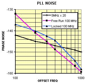
Phase-locking two ultra-low noise oscillators is an effective way to achieve excellent noise performance both close-in and at the noise floor. To illustrate the technique, this note describes a PLL using a 5 MHz ULN as the reference and a 100 MHz ULN as the locked oscillator. The 5 MHz reference exhibits superior phase noise, even after multiplication, for offset frequencies below about 300 Hz and the 100 MHz oscillator has better noise for offsets above 300 Hz. By setting the loop bandwidth near 300 Hz the locked 100 MHz phase noise is optimized.
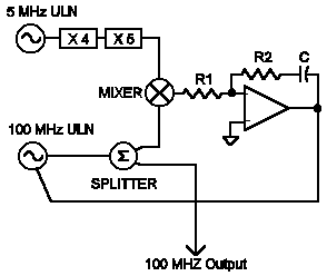
The block diagram is shown below. The 5 MHz oscillator is multiplied up to 100 MHz instead of dividing the 100 MHz oscillator down to 5 MHz to avoid running into noise floor limitations: the 100 MHz oscillator has a floor near -180 dBc and, after dividing by 20, the theoretical noise would be -206 dBc which is far below the noise floor of any dividers, mixers, etc. The frequency multipliers are a x 4, LNHQ and a x 5, LNOM and this multiplier chain degrades the 5 MHz ULN only slightly at frequencies above the loop bandwidth. The PLL circuitry is contained within a phase-locking module from the LNPLL series and consists of a Schottky diode double-balanced phase detector with a sensitivity of about 1 volt/radian followed by a low-noise lossy integrator. Not shown in the block diagram is a lowpass filter consisting of a 1 uH choke and a 1 uF capacitor connected between the mixer and R1. The time constant of this filter is far above the loop bandwidth and it does not significantly affect the loop.

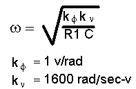
The tuning sensitivity of the oscillator is about 250 Hz/ volt which is about 1600 rad/sec-volt. C is chosen to be 0.2 uF which will give a fairly low value for R1 which helps reduce noise added by the PLL. The bandwidth of this type-2 PLL may be calculated from:
 |
|
The desired bandwidth of 300 Hz is 1900 radians/sec which gives a value of 2.2 k for R1 in the equation above. The loop damping is set by R2 and is adjusted to be fairly high to reduce noise peaking at resonance. A value of 15 k gives a damping factor near 3. For frequencies well below 300 Hz the locked 100 MHz oscillator closely follows the noise of the multiplied 5 MHz oscillator and for frequencies well above the 300 Hz bandwidth the locked oscillator’s noise approaches its free-running value, reduced only by the effects of the power splitter. The plot below shows the noise for frequencies between 100 and 1 kHz where the transition occurs. Note that the noise is about 3 dB worse than the two free-running oscillators where the noise plots cross.

The PLL design is straightforward but care must be paid to several details to achieve optimum noise performance. The noise of the locked oscillator will be degraded if significant excess noise applied to the tuning input. This noise may be measured by connecting an audio analyzer to the op-amp output while the loop is locked. The observed noise may be “good” in that it may be the required correction signal to clean the spectrum of the locked oscillator below the loop bandwidth but for frequencies above the loop bandwidth this noise may be excess, that is, it may be due to component noise and may be avoidable. To determine whether the observed noise is possibly responsible for the locked phase noise spectrum, calculate the phase noise that would result from the measured noise if it were random. First, measure the tuning sensitivity of the oscillator in parts/volt:.
A 1 ppm/volt sensitivity would be 1e-6.
Now multiply this sensitivity by the spectral density of the noise voltage at the frequency of interest:
100nV measured at 1 kHz offset would give 1e-6 x 100nV = 1e-13
This number is y(t), the fractional frequency noise. To obtain the “power” of this noise, Sy(f), simple square it:
1e-13^2 = 1e-26.
To calculate the phase noise spectral density, multiply Sy(f) by the carrier frequency squared and divide by the offset frequency squared:
1e-26 x 100MHz ^2 / 1kHz ^2 = 1e-16.
This operation converts fractional frequency to fractional phase and the numbers are squared because y(t) was squared earlier.The order of the calculation could be modified, if desired. To convert to dBc, simply take the log and multiply by 10:
10 log (1e-16) = -160 dBc (Subtract 3 dB to get the familiar L(f) = -157 dBc)
In the example the phase noise due to the observed noise on the tuning would be -157 dBc. If the oscillator should be much better than this level and the reference is better or not in control at this offset, the noise is probably due to excess noise. It may be tempting to try to low-pass filter this noise to prevent it from reaching the oscillator but such efforts will result in loop instability if the roll-off is near the loop bandwidth. It is typically necessary to use other noise reduction techniques. Select a low noise op-amp for the integrator and use fairly low value resistors to avoid converting op-amp noise current into significant noise voltage and to avoid the resistors’ thermal noise. (A 1k resistor has about 4 nV/Hz noise at room temp. and this noise varies with the square-root of resistance: i.e., a 100k exhibits about 40 nV.) Choose a low noise mixer (usually a Schottky diode type) with a reasonably high phase slope to avoid high amplifier gain. AC logic works reasonably well if the power supply is well filtered and the input waveform is properly conditioned. Avoid frequency dividing the oscillators since most dividers cannot support the noise of better oscillators, and the requirements on the following circuitry increases by the square of the division factor (6 dB per octave, 20 dB per decade). And finally, make sure that the mechanism for connecting the oscillators to the mixer doesn’t add significant noise. In some cases, degradation is unavoidable: the 100 MHz ULN above has such a low noise floor (actually better than -180 dBc) that an ordinary passive power splitter will degrade the noise. The LNPLL phase locking module contains a specially designed double-balanced mixer and low noise integrator along with performance monitoring circuitry.